Using Evaluation Kits to Implement a Current Source Circuit
Synopsis: Power Amp Design’s evaluation kits are normally configured to build voltage control application circuits, but it is also possible to build a current mode (transconductance) circuit as detailed in this article. Some knowledge of op amp circuit theory is assumed.
Operational amplifiers are designed to be voltage controlled circuits (voltage in, voltage out). Power Amp Design’s evaluation kit circuit boards are designed with voltage control circuits in mind. However, a transconductance (voltage in, current out) application circuit can be constructed as well using an evaluation board.
Op amp current source applications are less common but still an important application circuit. The two most common power op amp current source applications are the Howland current pump and the floating load current circuit. Simple schematics of these two op amp applications are shown in Figures 1 and 2, respectively.
The Howland current pump is the easier of the two circuits to implement using the evaluation kit board because the location of the current sensing resistance, Rs, is similar in both the voltage control and Howland current control application circuits. Therefore, this article will focus on the Howland current pump although the operation of the floating load current source will also be discussed briefly. Evaluation boards can also be adapted to the floating load current source but this circuit is much more difficult to construct and no details as to how to do this will be offered.
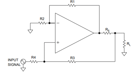
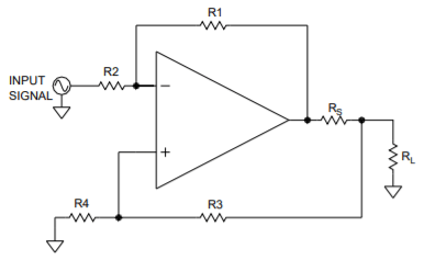
Simple Howland Current Pump Circuit (non-inverting)
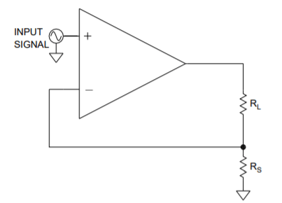
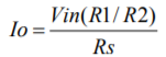
Simple Floating Load Current Control
In many applications the load must be grounded because of the way the load is physically constructed. The Howland current pump of Figure 1 is a suitable circuit for such circumstances. The scaling of the circuit is easy. First note in Figure 1 that R1 and R3 are to be the same values and R2 and R4 are the same values as well. As such the scaling of Figure 1 follows the equation:
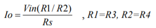
For example, if R1 and R3 are each 1kΩ , R2 and R4 are each 10kΩ and Rs is 100mΩ then 10V of input voltage will result in 10A of current in RL, or 1 amp output per volt of input, 1A/V.
As a practical matter, useful values of Rs between 10mΩ and 100mΩ work best, and the larger values work better overall. The limits of power dissipation in the sense resistor, Rs, must be kept in mind, because the power dissipation limit with the heat sink provided in the evaluation kit is 8-10 watts.
The selection of the sense resistor value is always a trade-off between power dissipation and circuit accuracy. The offset voltage of the amplifier appears across the sense resistor (multiplied by the circuit gain, if greater than 1) and so introduces a current error in the load.
For example, if the amplifier has an offset voltage of 5mV (including temperature drift) and the sense resistor chosen is 10mΩ, the current in load produced by the offset voltage will be simply
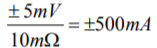
and this current will either add to or subtract from the current in the load demanded by the input voltage depending on the polarity of the offset voltage. As the value of the sense resistor increases the error current due to offset voltage decreases, but the power dissipation in the sense resistor increases.
There is another error current, namely, the current feedback in R3, but as a practical matter this current is usually negligible and can be ignored in most cases.
As you would expect, the tolerances of the various resistors also contribute to the error in the output current. Using 1% resistors tolerances usually gives satisfactory performance for gain error, but tighter tolerance resistors are not hard to find. Feedback resistor tolerances of 0.1% are easily obtainable. A sense resistor tolerance of 0.5 to 1% are also obtainable. The sense resistors supplied in the evaluation kits are in that range. Kelvin sense resistors are needed for current source applications due to the low values of the sense resistors in the circuits.
The Howland current pump can just as easily be configured for an inverting signal application by just reversing the connections to the inputs. Figure 3 below shows a schematic for an inverting Howland circuit.
A simple inverting Howland Current Pump
Likewise, the floating load current source of Figure 2 can also be reconfigured for inverting operation. See Figure 4 below.
The output current of Figure 4 is:
Inverting Floating Load Current Source
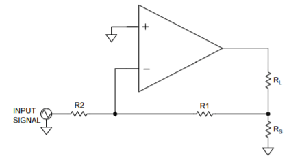
The final step is to implement a Howland current pump circuit (non-inverting) on an evaluation board. In Figure 5 below resistors R1, R2, R3 and R4 of Figure 1 have been added to the evaluation board. See the components in the magenta color. R1 and R3 of Figure 1 have been inserted into the holes in the board that connect these resistors to the sense pins of the Kelvin sense resistor Rs. The other ends of the resistors are connected with flying wires to the bread-boarding area. Also in the magenta color are resistors R2 and R4 to complete the current pump circuit. Figure 5, showing a modified EVAL117 board is a typical example to follow. Other evaluation kits have similar connections available. You can consult the schematic of the various models of evaluation kits. As time goes on Power Amp Design is converting our evaluation kits to include feedback points in the design of our evaluation kits to simplify implementing the Howland current pump circuit.
EVAL117 with Howland Current Pump Modifications (magenta)