Using the CJS01 Cage Jack Strip
Power Amp Design
Synopsis: This article provides details for using the CJS01 in the assembly operation of circuit boards.
It can be difficult or even impossible to remove power op amps from the mother board should one have to be replaced, especially in boards with plated-through holes. Attempting to remove the amplifier after soldering the pins can result in damaging the amplifier or circuit board or both. It is convenient therefore for the amplifier to be plugged into a socket.
The CJS01 is a 32 position strip of individual socket receptacles (cage jacks) just for that purpose. The CJS01 consists of two parts: the carrier strip and the individual sockets. Together the two parts are both the socket and an assembly aid.
The various amplifier models have different pin counts. The CJS01 can be easily cut to the required length with wire cutters. The 32 pin count strip can usually be cut into enough pieces to meet the total pin count of most amplifier models.
The assembly procedure is straight forward.
- Cut the CJS01 into sections long enough to match the pin count on each side of the amplifier.
- Insert each cut length into the corresponding holes in the circuit board from the same side of the circuit board that the amplifier will plug into.
- Provide some method where the CJS01 section is held tightly against the circuit board
- Solder the sockets from the other side of the board
- Remove and discard the carrier.
In applications where the CJS01 is used with circuit boards having plated-through holes it is often helpful first to coat the area with flux before inserting the cut strips. A flux pen is most convenient for this operation such as the Kester #2331-zx. The additional flux will help the solder flow all the way to the other side of the board so that solder will flow under the head of the socket.
You will notice that the sockets are open on the ends. The sockets therefore are not suitable for applications requiring wave soldering. The CJS01 sockets must be soldered by hand to avoid clogging the socket.
In many of the amplifier models several of the amplifier pins are connected together to improve the current handling capacity. The sockets therefore will be connected to common metal. These pads may be large and extra heat and/or a larger soldering iron tip may be needed to provide the heat necessary to melt all the solder on the pad. Adding the flux as mentioned above helps the solder flow over the entire pad without overheating the pad and insures that the solder flows to the other side of the board. For amplifier models with double rows of pins insert all the sockets in the double row before soldering.
The CJS01 datasheet provides dimensional information that should be used to design the circuit board pads. See figure 1 below for a recommended geometry for individual connections. As mentioned above, the pads may be connected with common metal where paralleled pins are required by the amplifier model.
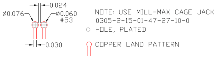
The CJS01 is loaded with Mill-Max cage jacks model 0305-2-15-01-47-10-0. You may also purchase directly from Mill Max the model 703-93-132-47-052100 which is similar to the CJS01.