Fine Tuning Current Limit
Power Amp Design
Synopsis: By necessity only a few values of current limiting sense resistors can be supplied with evaluation kits. This application note shows how to achieve intermediate values of current limit with the resistors supplied in our evaluation kits.
Power Amp Design’s evaluation kits include a limited number of current limit sense resistor values. Typical values are 10mΩ, 15mΩ, 50mΩ and 100mΩ, as provided in the EVAL117. Whether the PAD125 Current Limit Accessory Module is used or the built-in current limit circuit is used the typical values of sense resistor provide only a limited range of current limit set points. It is often desirable to achieve some intermediate value.
Fortunately, many of the evaluation kits are designed with locations where additional resistors can be added to the circuit to modify the current limit set point using a simple voltage divider network.
In Figure 1, the schematic of the EVAL117 is shown. Although each evaluation kit model has a somewhat different circuit, the components around the Rs resistor are the same for amplifiers with 4-wire current limit scheme and this same technique can be used with other evaluation kits or, indeed, your production circuit.
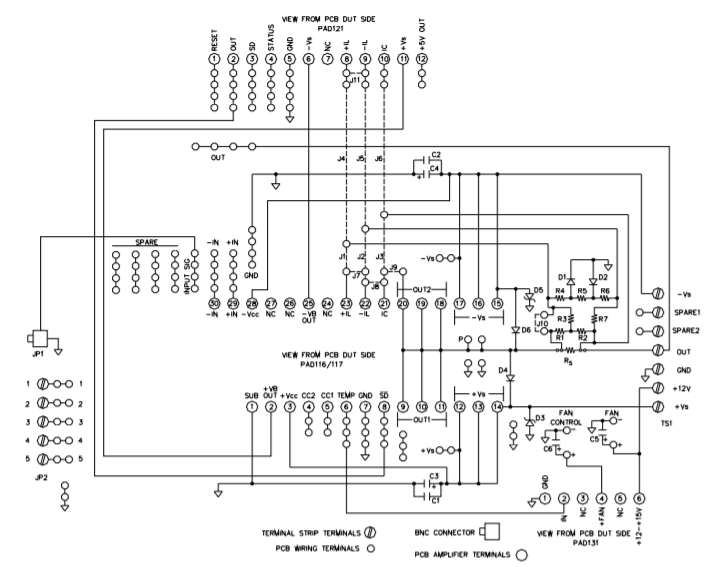
Circuit Diagram of the EVAL117 Evaluation kit
In the EVAL117 none of the components R1-R7 or D1, D2 are supplied. These components are used to implement a fold-over current limit scheme. But R1, R2 can also be used to modify the current limit set point that would otherwise be determined by Rs alone.
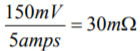
For example, let’s assume that the PAD125 Current Limit Accessory Module is being used in your circuit and you want to current limit at 5 amps. Since the current limit sense voltage of the PAD125 is 150mV, Rs would normally be determined by
A 30mΩ resistor value is not included in the EVAL117 evaluation kit, but we can still achieve the 5 amp current limit (or any other intermediate value). A suitable method for determining circuit component values to achieve a 5 amp current limit follows:
1) Select the next higher sense resistor provided; in this case a 50mΩ resistor (provided in the EVAL117 kit).
2) Assign a value of 50Ω to R1 as this will simply the arithmetic by reducing loading of the circuit.
3) Find the voltage developed across the selected Rs by the desired current limit value.
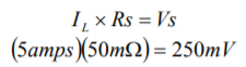
where IL is the desired current limit and Rs is the selected sense resistor value, and Vs is the voltage developed across the sense resistor.
4) And, finally, solve for the value of R2.
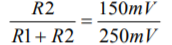
where 150mV is the sense voltage needed to trip the current limit circuit and 250mV is the voltage developed across the 50mΩ sense resistor that was selected.
R2 solves to be 75Ω.
To complete the circuit remove jumper J10 (or J3 in some evaluation kit models) and install a wire to jumper R3. Now, when 5 amps flows through Rs 150 mV will appear across R2 and the PAD125 will shut down the PAD117 at 5 amps output. It is the voltage across R2 that now provides the input voltage to the PAD125. Other ratios of R1 and R2 will, of course, give different current limit trip points. Since the values of Rs are so small, even small values of R1 and R2 will not much affect the accuracy of current limit set point and can probably be ignored since even the small values in this example are on the order of 1000 times greater that the sense resistor. The input impedance to the PAD125 is high and so this can also be neglected.
The final check you should make is for the power dissipation in Rs. In our example up to 5 amps could flow in Rs. The maximum power dissipation in Rs is then

Up to 8 watts dissipation in the heat sink for Rs is permissible so this total solution works.
This same technique also works when the internal current limit circuit is used in place of the PAD125 (for those models with an internal current limit option). The difference is that the internal current limit has a different sense voltage (approximately 0.65 volts) and is temperature dependent and not a precise as that of the PAD125.
Thus far we have discussed fine tuning the current limit for models having a 4-wire current limit capability. The 4-wire current limit scheme is characterized by the amplifier having current limit pins called +IL, -IL and IC. You can see these pins in the EVAL117 schematic where the pin-out of the PAD117 is shown.
Some other amplifier models do not have the 4-wire current limit capability and there is only one pin used for the current limit function and this pin is called IL. An example is the model PAD138. Below in Figure 2, is the schematic of the EVAL138, the evaluation kit for the PAD138.
Fine tuning of the current limit is still possible but the arithmetic is a little more difficult. In the schematic of the EVAL138 you will note that R1 and R2 are present, in parallel with Rs as was the case in the EVAL117 previously described. But in the case of the EVAL138 the divider network is loaded by the internal stage current of the PAD138 that is dumped into the current limit network during current limit. By the connections made in the EVAL117 this loading current was dumped directly into the load and therefore did not load the current limit sensing resistor network. These same connections are not possible in the case of the EVAL138 and PAD138 due to the fact that there is only one pin assigned to the current limit function. But this just makes the calculation more difficult and somewhat less precise.
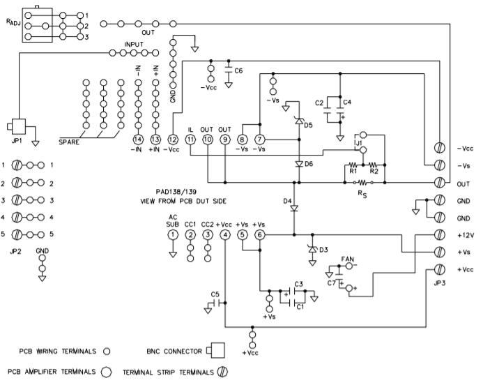
EVAL138 Schematic
In the EVAL138 several current limiting resistors are provided: one 100mΩ, one 200mΩ and one 500mΩ. The current limit circuit is not a precision circuit but the approximate current limit value can be determined by:

Where IL is the desired current limit value and Rs is the current limit sense resistor value
Using the supplied current limit sense resistors (Rs) the current limit values obtainable are:
RS ≈IL
100mΩ 7.0A
200mΩ 3.5A
500mΩ 1.4A
But suppose the desired current limit point is 2A. The values supplied in the EVAL138 will not give you a 2A current limit but we can achieve that with the R1, R2 divider.
A suitable method for determining the values of R1 and R2 in Figure 2 is to first determine the largest supplied value of Rs that would give you something less that the current limit value you desire. For example, if you wanted a current limit value of 2A you would select the 500mΩ resistor supplied in the EVAL138 kit. Next, assign R1 a value of 50Rs (this assignment keeps the power dissipation of R1 within the ¼ watt rating of common resistors) and solve for R2 in the following equation:
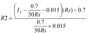
Where IL is the desired current limit value and Rs is the current limit sense resistor value. The 0.015 constant is the average loading current from PAD138 that is dumped into the current limit resistor network during current limit. For other amplifiers this number will probably be different. The 0.7 constant is the current limit sense voltage set by the internal sensing circuit. This constant may also vary a little with other models.
In this example, when a current limit of 2A is desired Rs is 500mΩ, R1 is 25Ω (50Rs) and R2 is 6.477Ω. Standard 1% values of 24.9Ω and 6.49Ω are adequate substitutions.
The exact desired value of Rs is often hard to find and this technique can be used to fine tune the current limit set point to most any value desired.