AN-34
Force & Sense Application for Power Op Amps
Power Amp Design
Synopsis: The article details a force and sense application for power op amps using a familiar differential amplifier application for IC small signal circuits. Some familiarity with op amp circuits is assumed.
Power op amp circuits often require a substantial load current of several amps or even tens of amps. In addition, the load is often at some distance from the output of the power op amp. The resulting IR losses in the connections decrease the voltage across the load. When an accurate voltage at the load is required it is wise to use the power op amp as a differential amplifier to cancel the IR losses. The feedback to the amplifier will guarantee the required voltage is across the load.
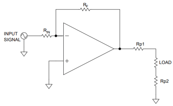
In Figure 1, the amplifier is connected to the load through the inevitable parasitic wire resistances Rp1 and Rp2 in the output of the amplifier and also the ground connection of the load. Since the feedback to the amplifier is applied locally at the output of the amplifier the voltage drop created by Rp1 cannot be corrected. Also, no correction for the voltage drop across Rp2 is possible with this circuit.
In Figure 2, the power op amp is configured as a differential amplifier. Due to the gain setting resistors 10R and R the circuit has a differential gain of 10. Any other gain would do as well. The circuit is inverting since the input signal is connected to the “minus” input of the amplifier. But the signal could just as well have been applied to the ‘plus” input of the amplifier for a non-inverting application.
“Force” and “Sense” are terms commonly referred to with this kind of circuit. The feedback connections to the amplifier are connected at the physical points to be controlled for voltage. In Figure 2, feedback to the inverting input of the power op amp is shown as “-Sense” and feedback to the non-inverting input of the amplifier is shown as “+Sense”. The output of the amplifier is referred to as “Force”.
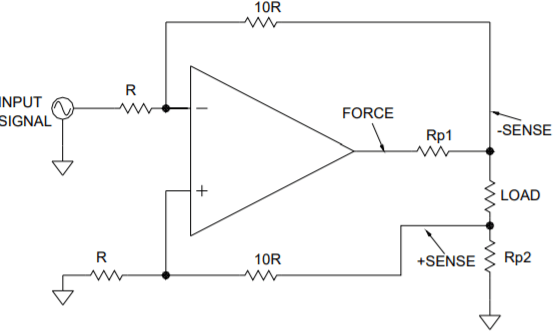
The circuit gives good accuracy with 1% resistors but it’s not difficult to find 0.1% resistors to improve the accuracy further. Either way, this differential circuit is a simple way to improve the accuracy of the voltage across the load compared with the circuit of Figure 1. With an output of 10 amps the voltage error across the load is 1 volt with 100mΩ of total parasitic resistance in the connections to the load. The circuit of Figure 2 will cancel that error with a
minimal cost in components.