AN-24
Eliminating Circuit Noise from Cooling Fans
Power Amp Design
Synopsis: The article covers the electrical noise considerations for connecting the cooling fan of Power Amp Design power op amps to the signal circuits.
Most power op amps currently produced by Power Amp Design rely on an integrated heat sink and fan to provide adequate cooling for the amplifier. The standard fan supplied with the amplifiers is a 12V brushless DC motor fan. Like all switching circuits, the brushless fan motor commutation generates electrical noise. If care is not taken in how the fan is connected to the amplifier circuit some of that electrical noise may appear at the output of the amplifier.
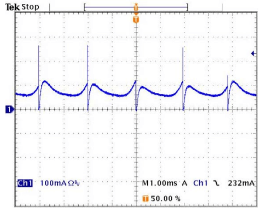
In Figure 1, below, the current in the return (minus) lead of the fan motor is displayed. The current spikes are approximately 250mA in amplitude. This is the source of the voltage spikes that can be observed in the output waveform shown in Figure 2.
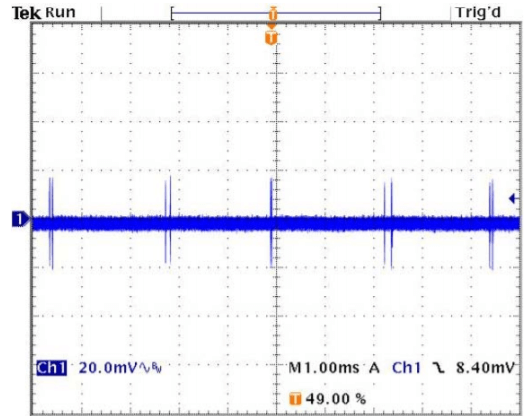
In Figure 2, the switching noise of the fan motor can be seen at the output of the amplifier. The noise is approximately 40mVp-p with the amplifier in a gain of 20. The amplitude of the noise will vary with the gain of the amplifier. The actual noise is often related to the input as RTI (referred to input). In this case a noise of 2mVp-p at the input will produce the output seen in Figure 2. The amplitude at the output of the amplifier will also depend on the rise and fall times of the current spikes.
Experiments have shown that this noise is injected into the amplifier’s common connection (ground) caused by the current spikes in the fan motor as shown in Figure 1. In many applications the noise is not objectionable, but it is easy to eliminate it altogether. The 12V power supply for the fan circuit is often isolated. Leaving this power supply isolated (its minus output not connected to the amplifier’s common) will eliminate the noise and no components are required. Another method is to connect a 47-100µF electrolytic capacitor on the circuit board directly at the physical point where the leads from the fan connect to the circuit. Twisting the fan lead wires into a twisted pair, while neat, does not reduce the noise, but it is good practice to cut the fan lead wires to the shortest practical length before attaching to the circuit board.
Circuit layout is also important. The waveforms in Figure 1 and Figure 2 were taken from an evaluation kit PCB with a ground plane connecting all the common connections for the circuit. Nevertheless, the fan motor current spikes were able affect the input to the amplifier. It is important that the return current from the fan motor not be mixed with the signal path common. A large ground plane and/or a single point ground connecting all the commons of the circuit will help reduce or eliminate any switching noise at the output of the amplifier.
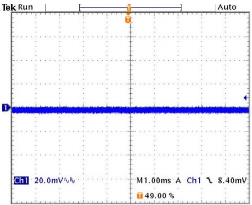
Figure 3 shows the result at the output of the amplifier of connecting a 47µF electrolytic capacitor directly at the point where the fan leads connect to the evaluation circuit board. The remaining noise is due to pickup of other noise sources. By a combination of careful circuit layout and adequate bypassing of the fan power supply connection all of the switching noise can be eliminated from the output of the amplifier.