AN-14
Cooling Power Op Amps
Power Amp Design
Synopsis: The article outlines the advantages of active cooling as compared to passive heat sinks in reducing the volume and weight of power op amps in industrial applications. The relative reliability of passive vs. active cooling is summarized. The advantages of pre-assembled amplifier and heat sink combinations are illustrated.
Unless your equipment is in outer space all cooling is ultimately accomplished by convection. In outer space there is no air so cooling is accomplished by radiation, but back here on earth the heat collected by whatever means is ultimately dumped into a cooler atmosphere. Liquids, for example, may carry heat away from power devices but in the end the heat passes through a radiator where cool outside air carries away the heat of the liquid. In a passive heat sink the heat generated in the power device is initially conducted through the metal body of the heat sink but convection eventually carries the heat from the heat sink fins to the atmosphere. True, back here on earth, there is a component of cooling resulting from radiation (and that’s why passive heat sinks are black, to simulate black body radiation) but overwhelmingly heat is carried away by convection.
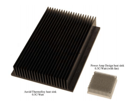
Board level passive heat sinks are prevalent and these are most often used to cool small transistors or ICs. But the limit for this type of heat sink is usually only a few watts. Larger transistors or ICs that dissipate tens of watts or more require large and heavy passive heat sinks. A more efficient way is forced air cooling. The differences between passive and active cooling can be dramatic. For example, Power Amp Design’s model PAD117 power op amp can be compared to a similar amplifier cooled with a passive heat sink.
Utilizing a small DC fan to force air into the heat sink the PAD117 provides a 0.5°C/Watt thermal resistance for the amplifier’s substrate with a volume of only 4.6 in3 and a weight of 4 oz. Aavid/Thermolloy has a passive heat sink extrusion available with a similar thermal resistance whose volume is 100 in3 and weighs in at 73 oz. A small DC fan that consumes only 1.5W (and excellent heat sink design) provides a rather dramatic improvement in weight and volume.
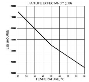
It may be argued that since the passive heat sink has no moving parts it provides a more reliable solution albeit an expensive one. But with modern DC brushless fans this reliability claim may be less than meets the eye. Power Amp Design uses ball bearing fans with a rating of 45k hours at a service temperature of 50°C. This equates to a L10 failure rate of 10% after 5 years of service at temperature (the L10 rating specifies the failure rate of a given population of fans after the specified period). As virtually the only mode of failure the quality of the ball bearings is key. And as the operating temperature falls the life of the bearing increases dramatically. See the chart below. In today’s fast moving markets it is quite possible that the life of the fan may exceed the life of the project.
Moreover, Power Amp Design amplifiers employ thermal sensing of the substrate and should the fan circuit fail resulting in a substrate temperature rise beyond 110°C the amplifier is shut off and an electronic flag is raised indicating a problem. Judicious monitoring of the flag signal will insure that although the fan circuit may fail the amplifier will not.
One other reliability concern often remains overlooked. The thermal interface between the amplifier’s substrate and the heat sink is critical. It is important that no voids exist in the interface and that the interface is as thin as possible. Thermal interface materials are poor thermal conductors compared to the metal substrates of the amplifiers and it is therefore imperative that it be as thin as possible to minimize thermal resistance. Therein hides a problem.
The most common method of providing the thermal interface is the manual application of some brand of silicone thermal grease. Directions for application of the grease always specify a thin layer of the grease. But the method for doing so is unclear. The grease must be as thin as possible but yet be assured that all the air pockets are eliminated and that any unevenness of the amplifier package or metal substrate are filled in. One method relied upon is to apply a generous thickness of the grease and then hope that once the package is screwed down to the heat sink that all the excess grease will be squeezed out the edges. Maybe. But this technique often both squeezes out some excess grease and bends the package or substrate at the mounting holes as well. Once the package is bowed the desired effect is gone for good.
The thermal interface of Power Amp Design products results from a different process. A preform of interface material was chosen that both expands and flows with pressure and heat. The preform is thicker than any expected variations in flatness of both the metal substrate and heat sink combined. The preform is sandwiched between the substrate and metal substrate and 100 pounds of pressure is uniformly applied while the heat sink and substrate assembly is heated to 60°C. After a time the thermal preform flows under the pressure filling in all irregularities in the metal substrate to heat sink bond line and expels any air bubbles. Excess material is squeezed out without bending or stressing the metal substrate. The result is that the thermal interface is both as thick as it needs to be and as thin as it can be. On average the thermal interface is 0.002” thick.
With Power Amp Design’s solutions to power op amp construction there is no need to specify, procure or assemble separate components. The difficult job of attaching the amplifier substrate to the heat sink is eliminated and the best attach that can be done is done by Power Amp Design’s approach to the problem.