AN-12
The Problem with Current Limit
Power Amp Design
Synopsis: Traditional current limiting circuits may not offer the operational amplifier the protection it needs to be reliable in an application circuit. The problems associated with one traditional current limiting circuit are analyzed and a new solution is explained featuring the PAD121 Current Limit Accessory module offered by Power Amp Design.
Pick most any monolithic op amp available and you will undoubtedly see specifications for maximum output current and short circuit current. The output current is most often limited by a simple transistor circuit that senses the drop across a small value resistor in the output path and this transistor circuit tugs on the drive to the output transistor to prevent it from supplying too much current. See Figure 1. The idea is to protect the amplifier from overheating that may destroy the op amp.
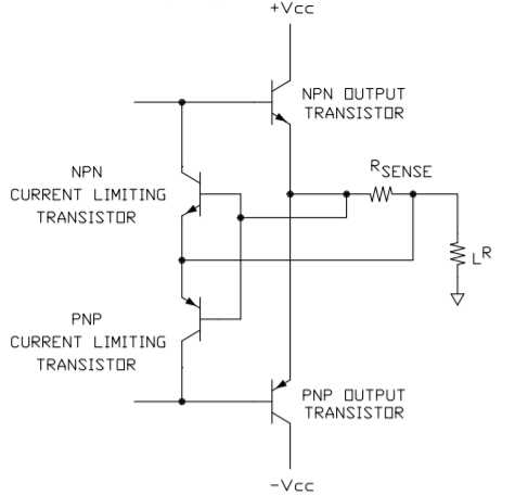
The advantages of this current limiting circuit are that few components (2 transistors and a sense resistor) are involved, the components don’t take up much area on the monolithic chip and therefore the circuit is cheap.
The most serious disadvantage of this circuit is that it doesn’t necessarily protect the amplifier. What usually destroys an amplifier is not the output current directly, but the power dissipation the amplifier must withstand while current limiting. More about this important point later.
And there are other disadvantages as well:
The circuit is not very accurate; a 20% or 30% tolerance can be expected. The wide tolerance means that the current limit must be set at least that much above the current level that is expected in normal operation.
The circuit is temperature sensitive. As the temperature of the amplifier rises the calculated trip point for current limit will decrease about .3%/°C. This also requires that the current limit set point be raised to accommodate the expected current at the maximum operating temperature.
The circuit may be non-symmetrical. Both NPN and PNP transistors are used in the circuit, the NPN to sense positive current and the PNP to sense negative current. The positive and negative current limit set points will follow the Vbe of the NPN and PNP transistors. The Vbe of these opposite sex transistors are usually not equal and that results in non-symmetric current limit trip points.
The sense voltage is approximately 0.6V-0.7V, the Vbe of a typical bipolar transistor. This voltage reduces the maximum output swing of the amplifier. Perhaps worse yet, amplitude of sense voltage can produce significant power dissipation in the current limit sense resistor when this technique is applied to power op amps. A 5-10W dissipation in the sense resistor for a power op amp circuit is not uncommon.
Now to address this circuit’s most serious flaw—that it does not necessarily protect the amplifier. Notice that once the amplifier has entered current limit the function of the op amp circuit shifts to that of a constant current amplifier. As far as the safety of the op amp is concerned this is dangerous territory. Consider Figure 2.
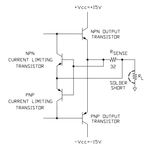
The output of the monolithic op amp has been shorted to ground by a solder bridge. The current limit has been set to 20mA. The NPN output transistor now has 14.4V across it while conducting 20mA. The resulting power dissipation in the output transistor is 288mW. Perhaps, instead, the solder bridge connects the output to the negative supply voltage. Now there is 588mW in the NPN output transistor. Will the monolithic op amp survive? Maybe yes, maybe no.
Let’s move away from the monolithic op amp and up a notch to the power op amp. Consider Figure 3.
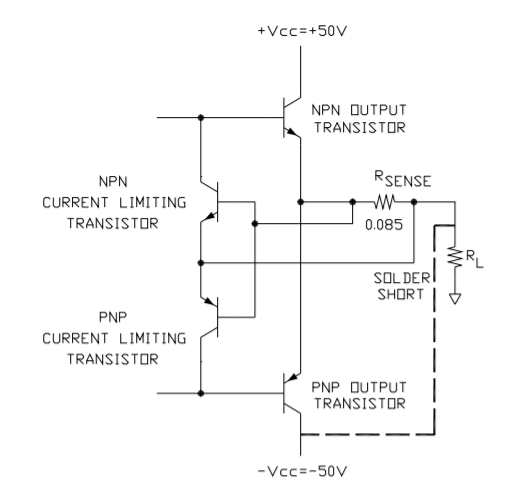
The supply voltages are +/- 50V and a similar current limit circuit is used and is set to trip at 7A. Just as in the example with the monolithic op amp let’s suppose a solder bridge has shorted the output to the negative supply voltage. The NPN output transistor of the power op amp now must dissipate 700W in order to survive. It won’t! Very shortly a puff of smoke may signal the end of the trail for this op amp.
One technique that helps protect the amplifier is dual slope current limit (fold-over current limit). As the voltage across the output transistor increases beyond some point the current limit value is reduced, thus helping the amplifier survive over-current conditions. See Figure 4.
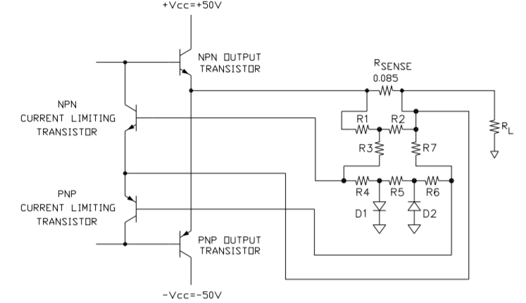
This is an improved current limiting technique but it does not eliminate the other disadvantages mentioned previously. The details of the operation of fold-over current limiting will not be discussed here but Power Amp Design has help available. See below.
A new technique developed by Power Amp Design in the PAD121 Current Limit Accessory Module advances the protection of power op amps. The problems of the old current limit circuit scheme have been reduced or eliminated by this external circuit.
The PAD121 addresses the limitations of the old current limit circuits by providing a host of new features:
The sense voltage has been reduced from the 0.6V-0.7V of the old circuit technique to a precision 150mV. Moreover, the sense voltage is temperature stable. The lower sense voltage reduces the power dissipation in the sense resistor to 25% or less of that with the old current limit technique. Three connections for the current limiting circuitry are brought out so that both 4-wire and fold-over current limiting can be implemented. Power Amp Design has developed a spreadsheet called PAD Power™ that calculates the values of the resistors for the fold-over current limit technique as seen in Figure 4 as well as many other design solutions. PAD Power™ can be downloaded from the website.
Whereas the old current limit circuit places the op amp into a constant current mode, the PAD121 shuts down the host amplifier. After all, the reason the current limit activates is because something is seriously wrong. With the old circuit the amplifier cooks at an elevated temperature or possibly cycles in an out of thermal shutdown until help arrives. Meanwhile the amplifier is operating at high temperatures which can reduce its reliability and wastes power besides.
The PAD121 operates differently. It shuts down the host amplifier and an alarm output signals that a problem has been found. Exactly how the host amplifier is shut down can be programmed by 1 or 2 passive external components. See Figure 5 below. With a jumper the PAD121 can shut down the host amplifier immediately or, alternately, the time constant of a resistor and capacitor can delay the onset of shutdown (R1, C1 in Figure 5). This feature can act as a slow blow fuse. After all, it’s possible that some short term over current condition might exist that does not violate the SOA (Safe Operating Area) of the amplifier. With this feature the over-current condition will be ignored for the time determined by the time constant of the chosen R and C. If desired it’s also possible to have the PAD121 reset itself after a time determined by the time constant of a second R and C circuit (R2, C2 in Figure 5). With the appropriate R and C the PAD121 could, for example, reset itself every 100mS. If the over-current condition has not gone away the PAD121 will shut down the host amplifier again. Lastly, an external logic signal can force the PAD121 to shutdown the host amplifier.
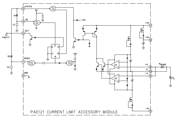
with External Programming.
The PAD121 was designed to interface with Power Amp Design models PAD117 and PAD118 power op amps. In the future, the PAD121 may interface with other models as well. In addition, connections for the PAD121 are incorporated into the evaluation kits for both the PAD117 and PAD118 power op amps.
One further advantage of the PAD121 compared to the old current limit circuitry is that the PAD121 better utilizes the available current capability of the power op amp. In the old circuit once the current limit trip point is set it acts on DC and AC signals equally. With the externally set time constant previously mentioned the PAD121 can be programmed to accept short term overloads within the SOA of the host amplifier. In the example while a DC current limit of 7A is programmed by the sense resistor a short term 10A or more might be within the SOA of the amplifier. This is especially useful, for example, when driving motors with the power op amp.